Showing posts with label Spectrum Measurement. Show all posts

Friday, 5 May 2017

What are String Pots?

Data acquisition system
String pots are intended to gauge direct uprooting. They are ordinarily lower cost than LVDTs and can offer any longer estimation separations. As their name suggests, the reason for string pot is a string or link, and a potentiometer. Fundamentally, a string and a spring are connected to the wiper screw of the potentiometer and as the string is pulled, the potentiometer resistance changes. The string pot gives an adjustment element that depicts what uprooting is spoken to by a rate of resistance change.
As a basic variable resistance gadget, with a direct yield, most string pots are interfaced to standard A/D sheets. The most widely recognized association arrangement interfaces a voltage reference to the one side of the string pot with the opposite side associated with ground.
The "wiper" is then associated with an A/D input channel. With the string totally withdrawn, the deliberate voltage will be equivalent to either reference voltage or zero. With the string totally developed, the voltage measured will be the inverse (either zero or the reference voltage). At any middle of the road string expansion, the voltage measured will be corresponding to the rate of string "out".
Make sure your voltage reference has the yield current ability to drive the string pot resistance. Your estimation will be a blunder by an indistinguishable rate from any voltage reference mistake. At times, it might be advantageous to drive the string pot with a higher limit, bring down exactness voltage source. Should you require higher exactness than the voltage source gives, you may dependably devote an A/D channel to quantify the voltage source.
This makes the framework for all intents and purposes safe to blunders in the voltage source. Another note is that string pots are single finished, disengaged gadgets. While associating a string pot to a differential information, make sure to interface the string pot/reference ground and the A/D channel's low or "- " input. Neglecting to make this association somehow will probably bring about problematic and even "odd" conduct as the information "- " terminal buoys all through the info enhancer's normal mode go.

Wednesday, 12 April 2017

Other types of DAQ Hardware - Part 3

daq

Output Drive

Make certain to research how much momentum is required by whatever gadget you are endeavoring to drive with the analog yield channel. Most D/A channels are restricted to under ±5 mA or ±10 mA max. A few merchants offer higher yield streams in standard yield modules (e.g., UEI's DNA-AO-308-350 which will drive ±50 mA). For higher yield still, it is frequently conceivable to include an outer cushion intensifier. Take note of that on the off chance that you are driving more than 10 mA, you will probably need to indicate a system with sense leads in the event that you have to keep up high system exactness.

Output Range 

Another genuinely evident thought, the yield run must be coordinated to your application prerequisite. Like their analog input kin, it is feasible for a D/A channel to drive a littler range than its maximum, however, there is a decrease of powerful resolution. Most analog yield modules are intended to drive ±10 V, however a few, similar to UEI's DNA-AO-308-350, will specifically drive yields up to ±40V. Higher voltages might be obliged with outside support gadgets. Obviously, at voltages more prominent than ±40V, wellbeing turns into a critical element. Be cautious — and if all else fails, contact a specialist who will help guarantee your system is sheltered. A last note with respect to expanding the yield scope of a D/A channel is that if the gadget being driven is either disengaged from the analog yield systems, or on the off chance that it utilizes differential inputs, it might be conceivable to twofold the successful yield run by utilizing two channels that drive their yields in inverse headings.

Output Update Rate 

In spite of the fact that numerous DAQ systems "set and overlook" the analog yield, numerous more require that they react to intermittent updates. In control systems, circle security or a prerequisite for control "smoothness" will regularly direct that yields be refreshed a specific number of times each second. Additionally, applications where the D/A's give a system excitation, a specific number of updates every second might be required. Check that the system you are thinking about is fit for giving the refresh rate required by your application. It is likewise a smart thought to incorporate somewhat cushion with this spec on the off chance that you find not far off you have to "turn" the yields somewhat speedier. 2.1.9 Output Slew Rate The second some portion of the yield "speed" determination, the large number rate, decides how rapidly the yield voltage changes once the D/A converter has been ordered to another esteem. Commonly indicated in volts per microsecond, if your system requires the yields to change and balance out rapidly, you will need to check your D/A yield slew rate.

Output Glitch Energy

As the yield changes starting with one level then onto the next, a "glitch" is made. Essentially, the glitch is an overshoot that consequently vanishes by means of hose wavering. In DC applications, the glitch is from time to time tricky, yet in the event that you are hoping to make a waveform with the analog yield, the glitch can be a noteworthy issue as it might produce significant commotion on any excitation inferred. Most D/A gadgets are intended to limit glitch, and it is conceivable to basically dispense with it in the D/A system, yet it additionally for all intents and purposes ensures that the yield slew rate will be reduced.

Sunday, 9 April 2017

Common Mode and CMRR

data logging software
The distinction between the "normal voltage" of the two differential inputs and the input ground is alluded to as the signal's Common Mode. Scientifically, the Common Mode voltage is characterized as Where Vhi is the voltage of the signal associated with the V+ (or VHi) terminal and Vlow is the voltage on the V-(or Vlow) terminal. The scope of input signals where the input can disregard or "reject" the Common Mode Voltage is known as the Common Mode Range.
Basic mode range is regularly determined in volts (e.g. ±10 V). On the off chance that both inputs stay inside this range, the differential input will work appropriately. Be that as it may, if either input stretches out past the range, the differential input enhancer will soak and make a significant and frequently erratic error. To keep your signals inside the normal mode run, you should guarantee that V+ added to Vcm is not as much as the maximum furthest reaches of the regular mode range and V-subtracted from Vcm is more prominent than the lower furthest reaches of the basic mode run. The capacity of a differential input to disregard or reject this Common Mode voltage and just measure the voltage between the two inputs is alluded to as the input's

Common Mode Rejection Ratio (or CMRR)

The Common Mode Rejection Ratio of present day input intensifiers is frequently 120 dB or more noteworthy
In our case, with a CMRR of 120 dB, the proportion is one section in one million. For every volt of Common Mode on the input, there is a Common Mode Error of 1 Microvolt. As should be obvious, basic mode can be overlooked in everything except the most delicate applications.

Friday, 31 March 2017

Temperature Measurements

Temperature data logger
Temperature is more likely than not the most ordinarily measured marvel in data acquisition. Regardless of whether the application is far below the ocean, on the interstate, noticeable all around, or in profound space, temperature assumes a key part in numerous systems. The most widely recognized temperature sensors are the Thermocouple, the RTD (Resistance Temperature Detector), the Thermistor, and the Semiconductor temperature sensor. Whole books have been composed with respect to temperature estimation and a top to bottom scope is past the extent of this article, yet we will offer the accompanying abridged exchange which ought to give enough data to most clients in many applications. 1.16.1 Which Sensor to Use?
Much of the time, more than one of the temperature sensor sorts would give the required outcomes. Be that as it may, considering just the accompanying variables will quite often indicate a reasonable most loved for a given application. These factors are:
• Accuracy / Sensitivity
• Temperature Measurement Range
• Cost
• System Simplicity
The Thermocouple (a.k.a. TC) is the workhorse of the temperature estimation world. It offers an exceed expectations loaned mix of sensible exactness, wide temperature measuring range, ease, and can be measured with straightforward inputs. The RTD offers extraordinary precision, repeatability, and a wide estimation run yet is genuinely costly and is to some degree complex to utilize. Curiously, thermistors run from extremely modest, low precision gadgets the distance to exceptionally costly, high exactness units. The thermistor measures temperature over a genuinely constrained range and is to some degree complex to utilize. At long last, the semiconductor sensor offers sensible precision, a restricted estimation extends, and can be observed with basic systems. Semiconductor sensors are likewise exceptionally reasonable.

Thursday, 26 January 2017

Spectra Resolution: Part 2

Spectrometer

When endeavoring to gauge the spectral resolution of a spectrometer guarantee that the deliberate flag is altogether slender to guarantee that the estimation is resolution constrained. This is regularly expert by utilizing a low weight discharge light, for example, a Hg vapor or Ar, since the linewidth of such sources is commonly much smaller than the spectral resolution of a dispersive exhibit spectrometer. In the event that smaller resolution is required, a solitary mode laser can be utilized.
After the information is gathered from the low weight light, the spectral resolution is measured at the full width half most extreme (FWHM) of the pinnacle of intrigue.
While ascertaining the spectral resolution (δλ) of a spectrometer, there are four qualities you should know: the opening width (Ws), the spectral scope of the spectrometer (Δλ), the pixel width (Wp), and the quantity of pixels in the indicator (n). It is likewise critical to recollect that spectral resolution is characterized as the FWHM. One exceptionally basic mix-up while figuring spectral resolution is to ignore the way that with a specific end goal to decide the FWHM of a pinnacle, at least three pixels is required, in this manner the spectral resolution (accepting the Ws = Wp) is equivalent to three circumstances the pixel resolution (Δλ/n). This relationship can be developed to make an esteem known as resolution variable (RF), which is dictated by the relationship between the opening width and the pixel width. As would be normal, when Ws ≈ Wp the resolution component is 3. At the point when Ws ≈ 2Wp the resolution calculate drops to 2.5, and keeps on dropping until Ws > 4Wp when the resolution figure levels out to 1.5.
For instance, if a spectrometer uses a 25µm opening, a 14µm 2048 pixel identifier and a wavelength extend from 350nm – 1050nm, the ascertained resolution will be 1.53nm.

Tuesday, 24 January 2017

Spectral Resolution: Part 1

Spectrometer
In the course of recent years, smaller than usual fiber optic spectrometers have advanced from an oddity to the spectrometer of decision for some cutting edge spectroscopists. Individuals are understanding the propelled utility and adaptability gave by their little size and similarity with a plenty of testing extras.
A standout amongst the most vital qualities of a spectrometer is the spectral (or optical) resolution. The spectral resolution of a framework decides the most extreme number of spectral pinnacles that the spectrometer can resolve. For instance, if a spectrometer with a wavelength scope of 200nm had a spectral resolution of 1nm, the framework would be fit for settling a most extreme of 200 individual wavelengths (crests) over a range.
In dispersive exhibit spectrometers, there are 3 fundamental variables that decide the spectral resolution of a spectrometer: the opening, the diffraction grinding, and the identifier. The opening decides the base picture estimate that the optical seat can shape in the locator plane. The diffraction grinding decides the aggregate wavelength scope of the spectrometer. The locator decides the most extreme number and size of prudent focuses in which the range can be digitized.
At the point when the flag linewidth is essentially more prominent than the spectral resolution, the impact can be disregarded and one can accept that the deliberate resolution is the same as the flag resolution. On the other hand, when the flag linewidth is fundamentally smaller than the spectrometer resolution, the watched range will be constrained exclusively by the spectrometer resolution.
For most applications it is protected to accept that you are working in one of these constraining cases, however for specific applications, for example, high-resolution Raman spectroscopy, this convolution can't be disregarded. For instance, if a spectrometer has a spectral resolution of ~3cm-1 and utilizations a laser with a linewidth of ~4cm-1, the watched flag will have a linewidth of ~5cm-1 since the spectral resolutions are so near each other (expecting a Gaussian appropriation).

Thursday, 1 December 2016

How it Feels to Manually Test

Automation
You’re hired! Great! You’ve got the job as a software quality assurance, just what you’ve wanted, right? Let’s take a look at your time spent at work, starting from day 1.

Day 1

You’ve happily walked into your office and there’s already a task waiting for you. Some application needs to be tested, and there are hundreds of forms, each with at least fifty-or-so fields, and even larger number of reports. That’s fine, you’re educated for all of that,  and you know what needs to be done. After an hour or so, you encounter an error. Perfect! You feel like you’ve already started contributing, you keep up with your work and find few more bugs by the end of the day.

Day 2

Like yesterday, you feel energetic, confident and ready to hunt down some errors. The bugs from yesterday were fixed, now it’s time to find if there are any more left. You pay attention to every detail and encounter more errors today, you’re getting better.

Day 3

A newer version of the app is out with minor bug fixes. You need to go all over again to check the same forms if there are any new errors. You start to feel a little bit bored, I mean, it’s the same mindless thing all over again.

Day 30

Fast forward to the end of the first month at your new job. New versions of the app come out every now and then, and you have to go through the same forms and reports all over again, countless times. You no longer feel energized and confident, you’re tired. Here and there, you begin to skip some of the steps, some bugs slip through, and you (as well as your employer) begin to question your competence. Let me stop you right there. You are not alone. Just like most of the SQA’s, you get in the phase where our “human” kicks in. You are not able to perform 100% accurately every hour, every day.
This is why we promote automated software testing, and this is just one of the reasons. ReadyDAQ’s automation technology will your and you’re employee’s precious time, money and energy. Why not invest those into something else?

Sunday, 13 November 2016

Tips for Improving Spectrum Measurement – Part 3

spectrometer

The third and the final part is finally here. We’ve gathered 3 more tips for spectrum measurement, and we conclude the series with this part. Hopefully, spectrometers won’t be that scary for you after reading this.

8. Watch out for RBW settings

The determination transmission capacity (RBW) control goes about as a channel permitting you to separate amongst wide and restricted signals in a similar traverse by changing the RBW esteem. On the off chance that RBW is too wide, the range analyzer will miss littler signals that may be shut into a bigger signal. With an extremely limit RBW, it can without much of a stretch separate the two signals that are near one another. In any case, a slender RBW will back off the range analyzer, implying that a more drawn out the signal term is required with a specific end goal to ensure the likelihood of block.

9. Real-time analysis helps to ensure that we notice randomly occurring events

Constant innovation is determined by the rate at which the yield can stay aware of the info. The range upgrade rate and the base occasion term are the key parameters. The execution is critical to having the capacity to see low-level signals and additionally signals inside a swarmed range; having the capacity to observe ranges and signals from each other. Higher execution range presentations can prepare more than 10,000 range redesigns every second, guaranteeing dependable disclosure of brief span occasions.

10. Density triggering should be used for time correlation of events

While the objective signal is missing, the thickness estimation describes the "typical" signals. At the point when the objective signal, at last, shows up, the thickness esteem increments. The trigger framework screens the thickness estimation and enacts a trigger at whatever point the thickness esteem surpasses the movable edge. The instrument can consequently set this edge to a level some place between the typical thickness readings and the thickness because of the inconvenience making a signal. This implies you can trigger on little signals even in a thick range environment.
Have you got any more of these tips? Please comment below or somewhere on our social media, we’d love to hear your insight.

Tips for Improving Spectrum Measurement – Part 2

spectrometer
We've started a new series of articles, this time about spectrum measurement. The second part brings four more tips to ease your everyday tasks with spectrometers. Enjoy!

4. Locating signals can be crucial

Utilizing a directional radio wire, the signal quality capacity on analyzers can empower you to characterize a particular signal inside a band of intrigue. As the level expands, the capable of being heard tonnes can permit you to boost the line of bearing. Urban areas are a specific issue since they are loaded with reflections. An ideal approach to adapt is to continue moving and to get however many lines of bearing as could be expected under the circumstances. The more lines of bearing, the littler the measure of vulnerability.

5. GPS Receiver is not the same as GPS Mapping

Attempting to make sense of where a signal or clamor is originating from can take quite a while. Geo-referenced estimations give situational information. With a GPS trigger motor, how regularly a signal happens and where it happens can be resolved to utilize either manual or mechanized drive estimations.

6. Signal identification can often not an easy task

A signal arrangement database can be utilized to recognize signals in light of their recurrence, involved transmission capacity and range signature, as appeared in the screen catch beneath, where the range analyzer could distinguish a signal as Bluetooth channel 39. Utilize the implicit library of signals and even modify it by adding your own signals to rapidly and unquestionably recognize signals.

7. Customizing your own signal database will spare you time in future

Attempting to distinguish a particular signal in a woodland of a spectrum is tough. A signal characterization database gives signal ID and also the way to stock your range data. You can stamp and recognize your range so that obscure emitters can be effectively identified.
No, we're not done with this! The third part is coming soon, make sure to check out our blog tomorrow!

Friday, 11 November 2016

Tips for Improving Spectrum Measurement – Part 1

Spectrometer
The things are changing. Spectrum is getting more and more crowded, so detecting a single source can be challenging sometimes. It is crucial that people measuring spectrums are equipped with the best hardware as well as software solutions for spectra measurement. We have prepared 10 tips to help you improve your experience while measuring the spectrum. Here’s the first part.

1. Wireless technologies are using time varying signals that fit into a crowded spectrum

Well-known advancements like Wi-Fi and Bluetooth utilize time-changing signs in their outlines to adjust for swarmed ranges and to decrease impedance issues. Conventional test devices, for example, cleared tuned range analyzers are not improved for these new innovations. Gifted administrators and specialists are required to utilize the customary devices. Performing range mapping and pursuing down an obstruction flag regularly should be done rapidly. Additional means like going back and stack information into a guide, for example, require some serious energy and back of the general procedure.

2. Strong interferers are able to block reception and overload A/D converters, a wide dynamic range is essential

One vital necessity for range administration hardware is to have adequate element range and selectivity to abstain from sticking from interferers firmly situated to the coveted recurrence. Solid interferers can immerse simple to-computerized converters (ADCs), obstructing the gathering of a craved powerless flag. Solid interferers can likewise make intermodulation items in an analyzer that anticipate effective investigation of the craved flag. Having adequate element run permits the flag analyzer to isolate frail flags within the sight of solid signs.

3. Phase noise is always there, but excessive noise could hide signals

An analyzer's inward stage commotion can likewise be an essential trait for some signal capture applications. Indeed, even with exceptional element run, if the analyzer's neighborhood oscillator (LO) stage commotion is not adequately low, a few signs might be difficult to get. The LO in the analyzer's collector can darken the sought powerless signal. Once clouded, the demodulator can no longer observe the two signals and resolve one from the other, and the weaker signal is lost.
The last tip concludes the first part of the series. We hope to improve your experience while using spectrometers. Stay tuned, the second one is coming very soon!

Friday, 30 September 2016

Save Time in Rapid Prototyping – Part Two

Data Logging
Here it is, the long waited part two of our tips on how to save time while – saving time (Yes, one of the goals of rapid prototyping is to save time on development). After you’ve learned about purpose and requirements of the prototype, as well as started thinking of it as a disposable artifact, it is time to introduce our next 3 steps to further improve your rapid prototyping experience.
Avoid working on interactions too soon
Unlike conventional “waterfall” model where it is recommended to start building UI as soon as possible, it is a waste of time in rapid prototyping. It will only create a huge amount of redundant work that will anyway get changed last minute before the deadline. Use the prototype to test what you need to test; UI will come natural at the end.
Test as you go
Wonderful thing about rapid prototyping is that it enables you to test things a lot faster and more often, plus, if there you stumble upon a dead-end, you can always go back and start again (Remember tip #1 from the previous article.) If you’ve done a lot of work without testing it, it may be hard to spot the exact place where things got wrong; so test, test, test, as often as possible.
Be swift
Don’t forget, it’s called rapid prototyping, so you need to honor its name and keep it fast and simple. The prototype will serve its purpose; it will get the desired results a lot faster than with using convectional “waterfall” methods. Just don’t lose your mind on some unnecessary details. Keep it rapid.
Congratulations, you’ve reached the end of the list! We hope that this series will help you and your team to stay focused on the task and to save two resources we’re always lacking – time and money.

Thursday, 29 September 2016

Light and Spectra Measurement in Microclimates

spectrometer

Photosynthesis is something we’ve all learned about back in elementary school, and, of course, the fundamental part of it is sunlight. Because it impacts plants so much, some farmers have started using technology to measure the quality and quantity of light in order to get the best possible results from their crops.
No, we cannot do it with our eyes. Our eyes are naturally programmed to adapt to light conditions, thus making it impossible to determine the actual amount and intensity of the sunlight. Measurement is necessary. The most efficient way to measure light (when it comes to plants) is in a specific frequency band called PAR (Photosynthetically Active Radiation), also known as quantum meters and their values are presented in micromoles.
Many spectrometer measure and calculate the intensity of light in a single moment for a single location. If we compare light in a specific field to a rainstorm that is measured with a rain gauge, the quantity of light is determined using a data logger with a light sensor.
Some research studies have shown that bench level lighting in a greenhouse could be lowered by whooping 35-70% over several year due to numerous factors: dust, dirt, poly decline, glazing, hanging baskets, and even the trees outside have the responsibility. Are you planting fields without taking advantage of the available technology? Start using it now!
ReadyDAQ cannot plant your crops, but we can create software; and not just any software, the best software based on LabVIEW and certified by National Instruments as a guarantee of the quality. Try our ReadyDAQ logger lite product for free, we have a 30-day trial version, and let us know what you think. Also you can use our ReadyDAQ for spectrometer product.
 

Wednesday, 28 September 2016

The Basics of Optical Spectrum Analysis

spectrometer

The measurement and analysis of any optical signals is not an easy task, and probably the hardest one is spectrum analysis. However, engineers and scientists gain valuable information from it, and that’s why the good spectrometer is an important factor for every project that requires spectrum measurement.

You’re probably wondering how does such a device work? Well, it sounds simple, a grating, which is the essential part of every spectrometer, splits the light into its components or wavelengths. The light travels through the mirror and reaches photodetector bar- a device which turns photons into electrical signal and a software interprets them to measure their strength.Sounds simple, right?

With that kind of view of the spectrum, it is not that hard to measure a signal’s frequency, power, modulation, harmonic content, spurs, as well as spectral noise. With these details, total harmonic distortion, occupied bandwidth, signal stability, output power, inter-modulation distortion, power bandwidth, carrier-to-noise ratio, and a host of other measurements then can be seen using a spectrometer. 

Basic understanding of how do spectrometer work is necessary to operate one. Once mastered, they are an extremely useful tools and can help with characterizing and analyzing various devices and systems.
 
ReadyDAQ has recently announced the release of the software for spectrometers. This software allows users to watch as well as record numerous sequential spectrums, even with delay, and to find a peak in every single one of them for measuring pn-junction temperature of semiconductor devices for example. The software is highly customizable, allowing users to view the collected data in a graph, or to observe spectrums in a continues mode.

SUMMARY:
The measurement and analysis of any optical signals is not an easy task, and probably the hardest one is spectrum analysis. Basic understanding of how do spectrometer work is necessary to operate one. Once mastered, they are an extremely useful tools and can help with characterizing and analyzing various devices and systems.


Wednesday, 7 September 2016

What Is Spectrum Measurement and How Is It Done?


data logging

Spectrum analyzers, according to Wikipedia, “measure the magnitude of an input signal versus frequency within the full frequency range of the instrument. The primary use is to measure the power of the spectrum of known and unknown signals.

Now you probably want that translated into English, right? In other words, the light goes through or reflected from a medium, and spectrometers are “breaking” the light into smaller components trying to get hold of as much information as possible. These components are the spectral power per wavelength.

However, it is not enough to just have a tool to measure the spectrum. Data logger are necessary to collect and store the information for further evaluation.

If you’re on a mission to analyze a spectrum, you need an amazing software that will provide the best possible results. That’s where ReadyDAQ comes in to save the day!
Our software ReadyDAQ for spectrometers will allow users to record numerous spectrums in a row, watch them in slow-motion and detect the peak of every spectrum. Sounds handy!
And that’s just the beginning. Companies developing products based on laser diodes will probably need to have the exact information about PN junction temperature presented in a graph. ReadyDAQ (daq) has got that covered too! This software makes data acquisition simple and perfect.
Is that not enough for you? Contact us for more details today!

SUMMARY:
Spectrum analyzers, according to Wikipedia, “measure the magnitude of an input signal versus frequency within the full frequency range of the instrument. The primary use is to measure the power of the spectrum of known and unknown signals.
Now you want that translated into English, right? Read the full article to understand spectrum analysis better.

STATUS UPDATE:
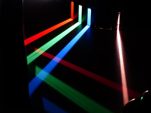
The process of breaking light up into a spectrum is "like passing white light through a prism." This process, called dispersion, arises because different colors (or wavelengths) of light bend by different amounts as they pass from, say, a low density medium (like air) into a higher density medium (like the glass in a prism). Hence, a narrow beam of "white" light will get spread out into a rainbow. Voila, a spectrum!