Friday, 31 March 2017

Temperature Measurements

Temperature data logger
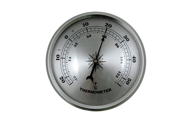
Temperature is more likely than not the most ordinarily measured marvel in data acquisition. Regardless of whether the application is far below the ocean, on the interstate, noticeable all around, or in profound space, temperature assumes a key part in numerous systems. The most widely recognized temperature sensors are the Thermocouple, the RTD (Resistance Temperature Detector), the Thermistor, and the Semiconductor temperature sensor. Whole books have been composed with respect to temperature estimation and a top to bottom scope is past the extent of this article, yet we will offer the accompanying abridged exchange which ought to give enough data to most clients in many applications. 1.16.1 Which Sensor to Use?
Much of the time, more than one of the temperature sensor sorts would give the required outcomes. Be that as it may, considering just the accompanying variables will quite often indicate a reasonable most loved for a given application. These factors are:
• Accuracy / Sensitivity
• Temperature Measurement Range
• Cost
• System Simplicity
The Thermocouple (a.k.a. TC) is the workhorse of the temperature estimation world. It offers an exceed expectations loaned mix of sensible exactness, wide temperature measuring range, ease, and can be measured with straightforward inputs. The RTD offers extraordinary precision, repeatability, and a wide estimation run yet is genuinely costly and is to some degree complex to utilize. Curiously, thermistors run from extremely modest, low precision gadgets the distance to exceptionally costly, high exactness units. The thermistor measures temperature over a genuinely constrained range and is to some degree complex to utilize. At long last, the semiconductor sensor offers sensible precision, a restricted estimation extends, and can be observed with basic systems. Semiconductor sensors are likewise exceptionally reasonable.
Thursday, 30 March 2017

Gain Error and Differential non-linearity

data acquisition

Gain Error 

It is least demanding to delineate this error by first accepting every single other error are zero. Pick up error is the distinction in the slant (in volts per bit) between the genuine system and a perfect system. For instance, if the pickup error is 1%, the pickup error at 1 volt would be 10 millivolts (1 * .01), while the error at 10 volts would be ten circumstances as substantial at 100 millivolts.
In a genuine system where alternate errors are not zero, the pickup error is typically characterized as the error of the estimation as a rate of the full scale perusing. For instance, in our 0 – 10-volt illustration extend, if the error at 10 V (or all the more regularly at a perusing subjectively near 10 volts, for example, 9.99 V) is 1 millivolt, the pickup error determined would be 100*(.001/10) or .01%. For higher accuracy estimation systems, the pickup error is regularly indicated in parts per million (or ppm) as opposed to percent as it's somewhat simpler to peruse.
To figure the error in parts per million, just duplicate the input error isolated by the input go by one million. In our case over, the 0.01% would be proportional to 1,000,000 * .001/10 or 100 ppm. In spite of the fact that numerous items offer auto-alignment, which generously lessens the pickup error, it is impractical to kill it totally.
The robotized pick up adjustment is quite often performed with respect to an inside provided the reference voltage. The reference voltage will float after some time and any error in the reference will translate into a pickup error. It is conceivable to make references with self-assertively little errors. Be that as it may, as the pickup error gets little with respect to other system errors, it turns out to be financially unfeasible to enhance the reference precision. Notwithstanding the cost punishment required in giving the "pseudo impeccable" reference, one of the errors, if not the biggest, in many references is the float with temperature. The best way to take out this float is to keep up the reference temperature at a consistent level. This is costly, as well as requires a lot of force, which expands general system control utilization
Non-Linearity
As its name infers, non-linearity is the distinction between the diagram of the input estimation versus real voltage and the straight line of a perfect estimation. The non-linearity error is made out of two segments, basic non-linearity (INL) and differential nonlinearity (DNL). Of the two, essential non-linearity is normally the particular of significance in most DAQ systems. The INL particular is ordinarily given in "bits" and depicts the greatest error commitment because of the deviation of the voltage as opposed to perusing bend from a straight line

Differential non-linearity

Differential non-linearity depicts the "jitter" between the input voltage differential required for the A/D converter to increment (or decline) by one piece. The yield of a perfect A/D converter will augmentation (or decrement) one LSB each time the input voltage increments (or reductions) by a sum precisely equivalent to the system resolution. For instance, in a 24-bit system with a 10-volt input run, the resolution per bit is 0.596 microvolt.
Genuine A/D converters, be that as it may, are not perfect and the voltage change required to increment or abatement the computerized yield differs. DNL is ordinarily ±1 LSB or less. A DNL particular more noteworthy than ±1 LSB demonstrates it is workable for there to miss codes. Despite the fact that not as hazardous as a non-monotonic D/A converter, A/D missing codes do trade off estimation exactness

Wednesday, 29 March 2017

Analog Inputs and A/D Converters

daq
The analog input is the foundation of the data acquisition showcase. In spite of the fact that other I/O ports play key parts in numerous applications, by far most of DAQ systems incorporate analog input and a decent percentage of they require just analog input.
We will characterize analog input by avoidance. Any input that is not computerized, that is not characterized as two states, (e.g., high/low or one/zero) will be viewed as analog. Normal analog inputs incorporate such estimations as temperature, weight, stream, strain and in addition the immediate estimation of voltage what's more, current.
Analog inputs are "measured" by a gadget called an A/D (Analog to Digital) converter (now and again
additionally alluded to as an ADC).
In spite of the fact that we'll talk about A/D converter innovation in the following area, it might be helpful to say here that A/D and analog input are frequently utilized reciprocally when alluding
the same thing to a DAQ item. In like manner use, an analog input board and A/D board same thing
. So also, an analog input channel and an A/D channel play out a similar capacity.
A/D Converters
An A/D converter does precisely what its name suggests. It is associated with an analog input flag, it
measures the analog input and after that gives the estimation in advanced frame reasonable for use bya PC. The A/D converter is the heart of any analog input DAQ system as the gadget really plays out the estimation of the flag.
Resolution
The resolution of an A/D input channel depicts the number or scope of various conceivable estimations the system is equipped for giving. This determination is all around gave in
term of "bits", where the resolution is characterized as:
2 (# of bits) – 1. For instance, 8-bit resolution relates to a resolution of one section in 28
– 1 or 255.
For resolutions over 12-bit, the "- 1" term
turns out to be for all intents and purposes unimportant and it is dropped. A resolution of 16-bits relates zto one section
in 216 or 65,536. The base distinction in an estimation is one piece. This one piece is often alluded to as the Least Significant Bit or LSB.
At the point when joined with an input range, the resolution decides how little an adjustment in the input is identify capably. To decide the resolution in building units, essentially separate the scope of the input by the resolution.

Monday, 27 March 2017

Strain (& Stress) Measurements

data acquisition system
The Strain Gage (a.k.a. Strain Gage) is a standout amongst the most normally measured gadgets in data acquisition and DAQ systems. The strain is frequently measured as the real parameter of intrigue. On the off chance that the application is really keen on how much a protest grows, contracts, or winds, the coveted estimation is a strain. The strain is likewise as often as possible measured as a moderate intends to gauge stretch, where stress is the constraint required to actuate a strain. Maybe the most widely recognized cases of this deciphered estimation are load cells, where the strain of a known, all around described metallic bar is measured, however, the genuine yield scale element of the cell is in units of the drive (e.g. pounds or newtons). The anxiety/strain relationship is all around characterized in numerous materials in specific designs, making the change from strain into stress a straightforward numerical figuring. Making matters less demanding still is that for some materials, including for all intents and purposes all metals, the connection amongst anxiety when the anxiety is connected in unadulterated strain or pressure is direct. The linearity of the relationship is alluded to as Hooke's law, while the genuine coefficient that depicts the relationship is regularly alluded to as either the modulus of flexibility or Young's modulus. Regardless of whether stress or strain is the real estimation of intrigue, the mechanics of the strain gage and the hardware required to make the estimation are for all intents and purposes indistinguishable. To make a basic strain gage, you require just immovably join a length of wire to the protest being stressed. In the event that connected in accordance with the strain as the question protracts under pressure, the wire to is extended. As the wire length expands so does its resistance. Then again, if the stressed protest is compacted, the length of the wire diminishes, and there is a relating change in the wire's resistance. Measure the resistance change and you have a sign of the strain changes of your protest. Obviously, the scale figure expected to change over the resistance change into strain would need to be resolved somehow, and it would not be an unimportant procedure. Additionally, the resistance change for a little strain change would be minuscule, making the estimation a troublesome one.
Today's strain gage producers have settled both the scale figure and, to a specific degree, the size of resistance change issues. To expand the yield (resistance change) per unit of strain, today's strain gages are normally made by putting numerous "wires" in a crisscross arrangement
A strain gage with 10 zigs and 10 zags would adequately build the yield scale consider by an element of 20 over the single wire case. For a straightforward application, you should simply adjust the strain gage so the "long" components are in parallel to the bearing of strain to quantify, and fasten the gage with a suitable cement.
The strain gage makers likewise furnish gages with extremely exact scale variables. This permits clients to change over the resistance estimation into strain, with a straightforward, direct condition (excluding temperature impacts… more on this later). The scale component of a strain gage is alluded to as its Gage Factor, which relying upon the source is usually curtailed as GF, Fg, or even K.

Calculate the Error and Eliminate It Mathematically

daq
On the off chance that you know the genuine distinction in coefficients of warm extension between the strain gage and the part being tried, it's hypothetically conceivable to numerically kill the error brought about by changes in temperature. Obviously, to do this, you likewise need to gauge the temperature precisely at the strain gage establishment. The strain gage development coefficients, in any case, are not for the most part accessible from the maker as they tend to change from clump to group. Despite the fact that conceivable, making up for temperature impacts utilizing just this "ascertained" strategy is at times done. More typical, yet at the same time not exceptionally normal, a pseudo-figured technique is performed. As opposed to utilizing a pre-or anticipated coefficient to ascertain the differential strain prompted by temperature transforms, it is conceivable to decide the capacity tentatively. The word capacity is utilized purposefully, as the real strain versus temperature bend is rarely straight, particularly over huge temperature changes. Notwithstanding, if the application permits the system's strain versus temperature bend to be resolved tentatively, it turns out to be genuinely clear to evacuate the error numerically.

Match the Strain Gauge to the Part Tested 

The utilization of various compounds/metals permits makers to give strain gages intended to coordinate the warm extension/withdrawal conduct of a wide assortment of materials generally subject to strain (and stress) testing. This sort of gage is alluded to as a "Self Temperature Compensated" (or STC) strain gage. These STC gauges are accessible from an assortment of producers and are determined for use in a wide variety of part materials. As you may envision, the more typical a metal, the better the odds are there is an STC gauge that matches. Notwithstanding, you may depend on having the capacity to locate a decent match for such materials as aluminum, metal, cast press, copper, carbon steel, stainless steel, titanium and some more. In spite of the fact that the match between the STC gauge and the part under test may not be flawless, it will regularly be sufficiently precise from solidifying to well past the breaking point of water. For more subtle elements on the exact precision to expect, you ought to contact your strain gage producer.

Use an Identical Strain Gauge in Another Leg of the Bridge 

Due to the ratiometric way of the Wheatstone connect, a moment, unstrained gage (regularly alluded to as a "sham" gauge) set in another leg of the scaffold will make up for temperature prompted strain. Take note of that the fake gauge ought to be indistinguishable to the "measuring" gauge and ought to be liable to a similar domain.
Strain gages have a tendency to be little, and have short warm time constants (i.e., their temperature changes rapidly in light of a temperature change around them), while the part under test may have generous warm mass and may change temperature gradually. Consequently, it is great practice to mount the fake gauge adjoining gage being measured. Be that as it may, it ought to be appended in such a route as not to be subjected to the initiated strain of the tried part. At times, with moderately thin subjects and when measuring twisting strain (instead of immaculate malleable or compressive strain), it might be conceivable to mount the spurious gage on the inverse side of a bar or pillar. For this situation, the temperature effect of the gauges is disposed of and the scale component of the yield is effectively multiplied.

Sunday, 26 March 2017

PC-based DAQ Systems

daq
PC-based DAQ systems are accessible with a wide assortment of interfaces. Ethernet, PCI, USB, PXI, PCI Express, Firewire, Compact Flash and even the respected GPIB, RS-232/485, and ISA transport are all prominent. Which one(s) is/are the most fitting for a given application might be a long way from self-evident. Maybe the primary question to address while considering another DAQ venture is whether the application is best served by a module board system or an outer "box" based system.
This issue has been a wellspring of much disarray (and rivalry) throughout the years, and the choice might be less all around characterized today than any time in recent memory. In the beginning of PC-based DAQ, the general guideline was: High-speed estimations were performed by board arrangements, high precision was the space of the outside box.
Obviously, there was a "dim" zone in the middle of that could be tended to by either frame figure.
Today's hazy area is significantly bigger than at any other time. Board level arrangements offering 24-bit determination are currently accessible as are 6.5 digit DMM sheets. On the crate side, USB 2.0 is hypothetically equipped for conveying 30 million 16-bit transformations every second and Gigabit Ethernet will deal with more than twice that. In spite of the fact that interior module opening data exchange rates have expanded 10 overlaps as of late, the regular data acquisition system test rate has not.
Planes and autos don't go substantially quicker now than in 1980 and temperatures and weights are still generally moderate evolving marvels. Since most application precision and test rates are splendidly inside the abilities of both board and box level arrangements, different contemplations will figure out which arrangement is best for a given application.
Some of these key factors, as well as why, will be listed in many upcoming articles!

Tuesday, 21 March 2017

Be Careful With Registrations

Labview projects
We found a memory development in their application which utilized client occasions for interprocess correspondence. The issue we found was that any client occasions which are enrolled however unhandled by an occasion structure will expand your application's memory use when produced.
A fundamentally the same as the issue was raised at the 2011 CLA summit that produced CAR 288741 (settled for LabVIEW 2013). This CAR was recorded in light of the fact that unhandled enlisted occasions really reset the timeout in occasion structures. There was a great deal of good dialog over at LAVA with clients estimating approaches to utilize this new component however what I didn't see raised anytime was the way that producing client occasions which are not taken care of in an occasion structure will bring about a memory development in your application notwithstanding resetting the occasion timeout.
From my understanding, we see this conduct on the grounds that the enlist occasions hub will make a post box for occasions to be placed in but since there is not a case in the occasion structure to deal with this particular occasion, it is never removed from the letter box. This will prompt an expansion in the application's memory each time that occasion is produced. I have backpedaled and forward between this being normal conduct and a bug. At the season of composing this I trust it not out of the ordinary conduct yet there are sure things that are either inconsistencies in LabVIEW or demonstrate my misconception of how LabVIEW occasions function.
One of these irregularities and a reason this issue can be so hard to find is the way unhandled occasions are shown in the Event Inspector Window.
The issue I have is that albeit "Some Event" is not dealt with in the occasion structure, it doesn't appear in the rundown of Unhandled Events in Event Queue(s). Curiously, the occasion shows up in the occasion log with the occasion kind of "Client Event (unhandled)" which implies LabVIEW knows the occasion is not taken care of in this specific occurrence but rather still keeps it in the post box. What is confounding, to me in any event, is that despite the fact that nothing appears in the occasion monitor's rundown of unhandled occasions, flushing the occasion line discards these occasions (additionally counteracting memory development).