Showing posts with label labview freelancer consultant. Show all posts

Monday, 18 December 2017

Engineers Turn to Automated Test Equipment to Save Time

http://www.readydaq.com/content/blog/engineers-turn-automated-test-equipment-save-time
With engineers rushing tests in order to hit tight product deadlines, the market for test equipment that automatically detects faults in semiconductors and other components is growing.
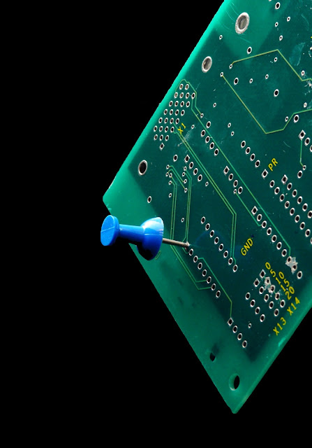
Setting aside time for testing has been a struggle for electrical engineers. The shrinking size - and increasing complexity - of semiconductor circuits is not making life any easier. Nearly 15% of wireless engineers are outsourcing final testing and more than 45% contract manufacturing – when most semiconductor testing takes place.
Almost 65% of the survey respondents said that testing is still a challenge in terms of time consumption. New chips designed for tiny connected sensors and autonomous cars also require rigorous testing to ensure reliability.
Tight deadlines for delivering new products is forcing engineers toward using automated test equipment, also known as ATE, to quickly identify defects in semiconductors, especially those used in smartphones, communication devices, and consumer electronics.
The global automated test equipment market is estimated to reach $4.36 billion in 2018, up from $3.54 billion in 2011, according to Transparency Market Research, a technology research firm.
Automated test equipment is used extensively in semiconductor manufacturing, where integrated circuits on a silicon chip must be tested before it is prepared for packaging. It cuts down on the time it takes to test more complex chips, which are incorporating higher speeds, performance, and pin counts. Automatic testing also helps to locate flaws in system-on-chips, or SoCs, which often contain analog, mixed-signal, and wireless parts on the same silicon chip.


Wednesday, 6 December 2017

Exploiting LabVIEW Libraries


labview expert
Have you ever viewed a LabVIEW VI Hierarchy and become frustrated with not being able to locate a VI you needed to open?
Do you have large applications composed of similar modules but fear to jump, with both feet, into the learning curve of LVOOP?
Did you ever try to duplicate a sub-VI at the start of a new set of functions and find yourself deep in a nest of cross-linked VIs, or save a VI only to realize that the most suitable name has already been used?
Then using LabVIEW Libraries may be useful to you
Libraries are a feature available in the LabVIEW project or they can be created stand-alone*. They have a number of features that allow you to specify shared properties and attributes of related VIs and custom controls.
In short, many of the features of LVOOP are available without the complications required for Dynamic Dispatching. The remainder of this document will serve as a tutorial that demonstrates how to create, define, and clone a library. Additional notes are included to illustrate how these features can be exploited to help you develop more robust applications that are easier to support than applications that do not use libraries.
*Libraries can be created stand-alone from the LabVIEW splash screen using the method:
File >>> New … >>> Other Files >>> Library
You can create a new library from the project by right-clicking the “My Computer” icon and selecting “New >>> Library”. Save it to a unique folder that will contain all of the files associated with the library.
Open the properties screen and then open the icon editor) to compose a Common Icon for the library and its members.
Take a little time to create the icon because it will be shared by all of the members of the library. Do not get carried away and fill-up the entire icon. Leave some white space so that the icons of the component VIs can be customized to illustrate their role in the functionality of the library.
Create virtual folders in the library to help organize the VIs contained in it. I usually use three folders but you can use more or less depending on your needs and preferences. I use one to hold the controls, and another pair for the public and private VIs. I do not use auto-populating folders for a number of reasons.
I can control which VIs are included and which are not. Occasionally temporary VIs are created to do some basic testing and they are never intended to be part of the library. If functionality changes and the temporary VI breaks due to the change, the library may cause a build to fail due to the broken VI.
I can easily move a VI from private to public without having to move the VI on disk and then properly updating source code control to reflect the change.
I can keep the file paths shorter using the virtual folders while maintaining the structure of the project.
Additional virtual folders can be added if you want to further break-down the organization of the VIs in the library. If developing a library that will be used by other developers and or be as a tool for others, you may want to include a folder for the VIs that define the API your library offers. The API can also be divided into additional virtual folders to break-down the interface into functional areas if you wish. Implement the Logical Grouping of sub-VIs as needed for your library.
Set the Access Scope of the private virtual folder to private. While the private folder and the setting of the access scope can be optional, taking advantage of this options will help you and the users of your library identify which VIs are not intended for use outside of the library. Attempting to use a VI with a private scope from outside the library itself will break the calling VI and make it very obvious that the VI is not intended for public use.
Developing applications using libraries differs little from developing without libraries with one exception; there is no additional work to use them. The exception is illustrated in Figure 8 where the name of the VI is highlighted. While the VI named in the project is shown as “Init_AI.vi” the actual name of the VI is “DAQ.lvib:AI.lvlib:Init_AI.vi”. The difference is the result of what is called “Name Mangling”. The actual name of the VI is prefixed by the library names that own the VI. This is a powerful feature that goes a long way toward avoiding cross-linking and will let us easily clone a library to be used as the starting point of a similar library.
The Save as the screen for the library will not only let us define the library name but also where in the project the library will be placed. This is handy for nested libraries but not critical. The libraries can be moved around in the project or between libraries as need using the project window. When a library is cloned using the Save As an option, all of the VIs contained in the original library are duplicated and re-linked to the VIs in the new library. There is NO chance of cross-linking when Cloning a library!
Libraries can help in all phases of an application from initial development to long-term support through to knowledge transfer. Remember, “Libraries” are your friend!

Wednesday, 30 August 2017

IoT: Standards, Legal Rights; Economy and Development

labview developers

It is safe to say that, at this point, the fragmented nature of IoT will hinder, or even discourage the value for users and industry. If IoT products happen to be poorly integrated, or inflexible regarding connectivity or are complex to operate, these factors can drive users as well as developers away from IoT. Also, poorly designed IoT devices can have negative consequences for the networks they connect to. Therefore, standardization is a logical next step as it can bring appropriate standards, models, and best practices. The standardization can, in turn, bring about user benefits, innovation and economic benefits.
 
Moreover, a widespread use of IoT devices brings about many regulatory and legal issues. Yet, since IoT technology is rapidly changing, many regulatory bodies cannot keep up with the change, so these bodies also need to adapt to the volatility of IoT technologies. But one of the issues which frequently comes in action is what to do when IoT devices collect data in one jurisdiction and transmit it to another jurisdiction with, for example, more lenient laws for data protection. Also, the data collected from IoT devices are often times liable to misuse, potentially causing legal issues for some users.
 
Other burning legal issues are the conflict between lawful surveillance and civil rights; data retention and ‘the right to be forgotten’; and legal liability for unaware users. Although the challenges are many in number and great in scope, IoT needs laws and regulations which protect the user and their rights but also do not stand in the way of innovation and trust.
 
Finally, Internet of Things can bring great and numerous benefits to developing countries and economies. Many areas can be improved through IoT: agriculture, healthcare, industry, to name a few. IoT can offer a connected ‘smart’ world and link aspects of people’s everyday lives into one huge web. IoT affects everything around it, but the risks, promises and possible outcomes need to be talked about and debated if one is to pick the most effective ways to go forward.

Sunday, 20 August 2017

LabVIEW Projects you should Know


labview
STÄUBLI LABVIEW INTEGRATION LIBRARY
The DSM LabVIEW-Stäubli Control Library is created to simplify communications between a host PC running LabVIEW and a Stäubli robotic motion controller so as to control the robot from the LabVIEW environment. 
Stäubli Robots are usually found in the automation industry. The standard Staubli programming language, VAL3, is an adjustable language allowing for a wide variety of tasking. Although the VAL3 language works well in its environment, there are limited options for connecting the robot to an existing PC-based test & measurement system. The LabVIEW language, on the other hand, has been created from the start to run systems found in a research environment. The DSM LabVIEW-Staubli Integration Library lets the user promptly create applications for a Staubli robot using the familiar LabVIEW programming language.
 
 
AUTOMATED CRYOGENIC TEST STATION
A test station was built with the intent in mind to automate cyclic cryogenic exposure.  A LabVIEW program was inserted to automate the process and collect data. The software featured:
Checked the temperature of up to 8 thermocouples
Checked the life status of test specimens twice per cycle
Automated backups to allow for data recovery
System was integrated with a pneumatic control board and safety features
 
 
TENSILE TESTER CONTROL PROGRAM
This system is able to record high-resolution x-ray imagery of test subjects of aerospace alloys while they are under tensile and cyclic fatigue tests.  This capability can improve understanding of how grain refinement is used to enhance material properties.  The tensile tester can function in multiple modes of operation. The sample can be fully rotated within the tester, permitting three-dimensional imagery of samples.
 
DYNAMOMETER TEST STATION
A test station designed to characterize piezoelectric motors was built, with programmable current source and a DC motor integrated into the system to apply a range of resistive torque loads to the tested motor.  A torque load cell and a high-resolution encoder were used to measure torque and speed, which is collected at each resistive torque level, forming a torque curve. A LabVIEW project was programmed to run the test. Test settings were configured in the program and data was collected by an NI DAQ card. The program also included data manipulation and analysis.
 
OPEN-LOOP ACTUATOR CONTROLLER
The goal is to characterize the actuator's performance in open-loop so that a closed-loop control scheme can be developed. This program can output voltage waveforms as well as voltage steps up to 40V. Voltage duration is programmable down to the millisecond and an encoder is integrated into the system and readings are real time. The encoder features resolution on a micron level and experiences exceptional noise due to the vibrations present in the system. The data is filtered after the test to report accurate, low-noise data.

Tuesday, 8 August 2017

Basics and Applications of Optical Sensor

professional labview expert
An optical sensor is one that converts light rays into a computerized signal. To measure a physical quantity of light and, depending on the sort of sensor, translate it into a form that is readable by some unified measuring device is the purpose of an optical sensor. Optical sensors can be both external and internal. External sensors assemble and address an appropriate quantity of light, while internal sensors measure the bends and other small changes in direction.

Types of Optical Sensors

There are various kinds of optical sensors, and here are the most common types.

Through-Beam Sensors

The usual system consists of two independent components. The receiver and the transmitter are placed opposite to each other. That transmitter projects a light beam onto the receiver. A breach of the light beam is explained as a switch signal by the receiver. It is insignificant where the interruption appears.
Its advantage is that large operating distances can be attained and the recognition is separated from the object’s surface structure, colour or reflectivity.
It must be assured that the object is sufficiently huge to interrupt the light beam completely, to ensure a high operational dependability.

Diffuse Reflection Sensors

Both receiver and transmitter are in one housing. The transmitted light is reflected by the object that must be identified.
The diffused light intensity at the receiver serves as the switching condition. Regardless of the sensitivity setting the front part regularly reflects worse than the rear part and this leads to the after effect of false switching operations.

Retro-Reflective Sensors

Here, both transmitter and receiver are in the same house. Through a reflector, the radiated light beam is conducted back to the receiver. An interruption of the light beam commences a switching operation. It is not influential where the interruption occurs.
Retro-reflective sensors set up large operating distances with switching points, which are completely reproducible demanding little escalating effort. Any object interfering the light beam is precisely detected independently of its colour or surface structure.

Thursday, 3 August 2017

How Stack Machines Meet the Needs of Various Systems

temperature data logger
There are various characteristics which need to be met in order for these machines to be suitable and to be fully and successfully implemented into real time systems. These characteristics are as follows: size and weight, power and cooling, operating environment, cost and performance.

Size and Weight 

It has been observed that stack computers are very simple in regards to processor complexity. However, it is the overall system complexity that determines overall system size and weight. The solution to overcoming the size and weight issue is to keep component count small. That is why stack machines are less complex than other machines and are also more reliable.

Power and Cooling

If the processor is complex, it can affect the amount of power it needs. That amount of power is related to how many transistors there are in a processor and how many pins are on the processor chip. Moreover, processors that need a lot of power-consuming high-speed memory devices can also be burdensome regarding power. Of course, power consumption directly affects cooling requirements, since all power used by a computer is eventually transmuted into heat. The cooler operation of processor components can reduce the number of component failures, thus improving reliability.

Operating Environment

Embedded processing systems are well known for extreme operating conditions. The processing system must deal with heat and cold, vibration, shock, and even radiation. Also, in remotely installed applications, the system must be able to survive without field service technicians to make repairs. The general rule to avoiding problems caused by operating environments is to keep the component count and a number of pins minuscule. Stack machines, with their low system complexity and high levels of integration, do well under these conditions.

Cost

Since the cost of a chip is related to the number of transistors and to the number of pins on the chip, low complexity stack processors are basically low in cost.
Computing Performance. Computing performance in a real time embedded control environment is not simply defined. Although raw computational performance is important, there are other factors which influence the system. An additional desirable feat is a fantastic execution in programs that are filled with procedure calls reducing program memory size.

How do RS-232, RS-422, and RS-485 compare to each other?

data acquisition device
RS-232 (ANSI/EIA-232 Standard) is the most widespread serial interface and it is used to ship as a standard component on most Windows-compatible desktop computers. Nowadays, it is more frequent to use RS-232 rather than using a USB and a converter. One downfall is that RS-232 only permits for one transmitter and one receiver on each line. RS- 232 also employs a Full-Duplex transmission method. Some RS-232 boards sold by National Instruments support baud rates up to 1 Mbit/s, but most devices are restricted to 115.2 kbit/s. On one hand, RS-422 (EIA RS-422- A Standard) is the serial connection employed primarily on Apple computers. It provides a mechanism for sending and receiving data up to 10 Mbits/s. RS-422 sends each signal employing two wires in order to increase the maximum baud rate and cable length. RS-422 is also specified for multi-drop applications where only one transmitter is linked to and sends and receives a bus of up to 10 receivers. On the other hand, RS-485 is a superset of RS-422 and expands on the capabilities of that previous model. RS-485 was manufactured to deal with the multi-drop limitation of RS-422, letting up to 32 devices to communicate through the same data line. Any of the subordinate devices on an RS-485 bus can communicate with any other 32 subordinate or ‘slave’ devices without the master device receiving any signals. Since RS-422 is a subset of RS-485, all RS-422 devices can be controlled by RS-485.
Finally, both RS-485 and RS-422 have multi-drop capability installed in them, but RS-485 allows up to 32 devices and RS-422 has a limit of only 10 devices. For both communication protocols, it is advisable that one should provide their own termination. All National Instruments RS-485 boards will work with RS-422 standards.

Friday, 7 July 2017

Setting up LabVIEW Project

labview freelancer consultant
Complete the following steps to set up the LabVIEW project:
 
  1. Launch LabVIEW by selecting Start»All Programs»National Instruments»LabVIEW.
  2. Click the Empty Project link in the Getting Started window to display the Project Explorer window. You can also select File»New Project to display the Project Explorer window.
  3. Select Help and make sure that Show Context Help is checked. You can refer to the context help throughout this process for information about items in the Project Explorer window and in your VIs.
  4. Right-click the top-level Project item in the Project Explorer window and select New»Targets and Devices from the shortcut menu to display the Add Targets and Devices dialog box.
  5. Make sure that the Existing target or device radio button is selected.
  6. Expand Real-Time CompactRIO.
  7. Select the CompactRIO controller to add to the project and click OK.
  8. Select FPGA Interface from the Select Programming Mode dialog box to put the system into FPGA Interface programming mode.
  9. Tip Tip  Use the CompactRIO Chassis Properties dialog box to change the programming mode in an existing project. Right-click the CompactRIO chassis in the Project Explorer window and select Properties from the shortcut menu to display this dialog box.
  10. Click Discover in the Discover C Series Modules? dialog box if it appears.
  11. Click Continue.
  12. Drag and drop the C Series module(s) that will run in Scan Interface mode under the chassis item. Leave any modules you plan to write FPGA code for under the FPGA target.

Real-Time Processor

professional labview expert
An industrial 400 MHz Freescale MPC5200 processor that deterministically acquires one’s LabVIEW Real-Time applications on the reliable Wind River VxWorks real-time operating system features the CompactRIO installed the system. Built-in operations for transferring data between the real-time processor within the CompactRIO embedded system and the FPGA are available in LabVIEW. One can pick from more than 600 built-in LabVIEW functions to frame its multithreaded installed system for real-time analysis, control, data logging, and communication. To save on development time, one can likewise combine existing C/C++ code with LabVIEW Real-Time code.

Starting a New CompactRIO Project in LabVIEW

One should commence by creating a new project in LabVIEW, where one can manage some hardware resources and code.
1.       By selecting File » New Project, one creates a new project in LabVIEW.
2.        Right-click on the Project feature at the top of the tree and by selecting New » Targets and Devices, one adds existing CompactRIO system to the project.
3.      One can add offline systems, or discover, by this dialogue, systems on existing network. To enlarge the Real-Time CompactRIO folder, select existing system, and click OK. Note: LabVIEW might not find it on the network if the existing system is not listed. Ensure that the existing system is well configured with a valid IP address in Measurement & Automation Explorer. One can likewise select to manually enter the IP address if the existing system is on a remote subnet.

Select the Appropriate Programming Model

Two programming models are granted by LabVIEW for CompactRIO systems. If one has LabVIEW FPGA and LabVIEW Real-Time on the existing development CPU, the one can be incited to pick which programming model he/she would like to use. In the LabVIEW Project, the one can change this setting later, if needed.
Scan Interface (CompactRIO Scan Mode) option allows a person to programme the real-time processor of the already existing CompactRIO system on a computer, but not the FPGA. NI provides a pre-defined personality for the FPGA that regularly scans the I/O and allocates it in a memory map, in this mode, making it accessible to LabVIEW Real-Time. For applications that lack single-point access to I/O at rates of a few hundred hertz, CompactRIO Scan Mode is sufficient. If someone wants to learn more about scan mode, the one should read the “Using CompactRIO Scan Mode” with “NI LabVIEW” white paper and sight the benchmarks.
LabVIEW FPGA Interface option allows a person to unlock the true power of CompactRIO throughout customising the FPGA personality in addition to the programming of the real-time processor and accomplishing performance that would typically lack custom hardware. One can implement custom triggering and timing, off-load signal analysis and processing, create custom protocols, and access I/O at its maximum rate by using LabVIEW FPGA.
After that, one should select the appropriate programming model for the existing application.
Consequently, LabVIEW will then try to detect C Series I/O modules present in the existing system and automatically add them to the LabVIEW Project and the chassis. Note: If a person’s existing system was not discovered and one chooses to add it offline, one will need to add the chassis and C Series I/O manually. For scan mode and FPGA mode, The LabVIEW Help online discusses this operation.

Tuesday, 30 May 2017

Introduction to RS232 Serial Communication - Part 1

Labview consultant
Serial communication is basically the transmission or reception of data one bit at a time. Today’s computers generally address data in bytes or some multiple thereof. A byte contains 8 bits. A bit is basically either a logical 1 or zero. Every character on this page is actually expressed internally as one byte. The serial port is used to convert each byte to a stream of ones and zeroes as well as to convert streams of ones and zeroes to bytes. The serial port contains an electronic chip called Universal Asynchronous Receiver/Transmitter (UART) that actually does the conversion.
The serial port has many pins. We will discuss the transmit and receive pin first. Electrically speaking, whenever the serial port sends a logical one (1) a negative voltage is effected on the transmit pin. Whenever the serial port sends a logical zero (0) a positive voltage is effected. When no data is being sent, the serial port’s transmit pin’s voltage is negative (1) and is said to be in the MARK state. Note that the serial port can also be forced to keep the transmit pin at a positive voltage (0) and is said to be the SPACE or BREAK state. (The terms MARK and SPACE are also used to simply denote a negative voltage (1) or a positive voltage(0) at the transmit pin respectively).
When transmitting a byte, the UART (serial port) first sends a START BIT which is a positive voltage (0), followed by the data (general 8 bits, but could be 5, 6, 7, or 8 bits) followed by one or two STOP BITs which is a negative(1) voltage. The sequence is repeated for each byte sent.
At this point, you may want to know what is the duration of a bit. In other words, how long does the signal stay in a particular state to define a bit? The answer is simple. It is dependent on the baud rate. The baud rate is the number of times the signal can switch states in one second. Therefore, if the line is operating at 9600 baud, the line can switch states 9,600 times per second. This means each bit has the duration of 1/9600 of a second or about 100 µsec.
When transmitting a character there are other characteristics other than the baud rate that must be known or that must be setup. These characteristics define the entire interpretation of the data stream.
The first characteristic is the length of the byte that will be transmitted. This length, in general, can be anywhere from 5 to 8 bits.
The second characteristic is parity. The parity characteristic can be even, odd, mark, space, or none. If even parity, then the last data bit transmitted will be a logical 1 if the data transmitted had an even amount of 0 bits. If odd parity, then the last data bit transmitted will be a logical 1 if the data transmitted had an odd amount of 0 bits. If MARK parity, then the last transmitted data bit will always be a logical 1. If SPACE parity, then the last transmitted data bit will always be a logical 0. If no parity then there is no parity bit transmitted.
A third characteristic is a number of stop bits. This value, in general, is 1 or 2.
Stay tuned for part two, it will be published soon.

Friday, 26 May 2017

Computerized Outputs

data logger
Digital Outputs require a similar investigation and large portions of indistinguishable contemplation from advanced data sources. These incorporate watchful thought of yield voltage go, greatest refresh rate, and most extreme drive current required. In any case, the yields likewise have various particular contemplations, as portrayed beneath. Relays have the benefit of high off impedance, low off spillage, low on resistance, irresoluteness amongst AC and DC flags, and implicit segregation. Be that as it may, they are mechanical gadgets and consequently give bring down unwavering quality and commonly slower reaction rates. Semi-conductor yields regularly have a favorable position in speed and unwavering quality.
Semiconductor changes additionally have a tendency to be littler than their mechanical reciprocals, so a semiconductor-based advanced yield gadget will commonly give more yields per unit volume. When utilizing DC semiconductor gadgets, be mindful so as to consider whether your framework requires the yield to sink or source current. To fulfill varying necessities,

Current Limiting/Fusing

Most yields, and especially those used to switch high streams (100 mA or something like that), offer some kind of yield security. There are three sorts most normally accessible. The first is a straightforward circuit. Cheap and dependable, the primary issue with circuits, is they can't be reset and should be supplanted when blown. The second sort of current constraining is given by a resettable breaker. Ordinarily, these gadgets are variable resistors. Once the current achieves a specific edge, their resistance starts to rise rapidly, at last constraining the current and stopping the current.
Once the culpable association is evacuated, the resettable circuit returns to its unique low impedance state. The third kind of limiter is a real current screen that turns the yield off if and when an overcurrent is recognized. This "controller" limiter has the upsides of not requiring substitution taking after an overcurrent occasion. Numerous usage of the controller setup additionally permits the overcurrent outing to be determined to a channel by channel premise, even with a solitary yield board.


Friday, 5 May 2017

What are String Pots?

Data acquisition system
String pots are intended to gauge direct uprooting. They are ordinarily lower cost than LVDTs and can offer any longer estimation separations. As their name suggests, the reason for string pot is a string or link, and a potentiometer. Fundamentally, a string and a spring are connected to the wiper screw of the potentiometer and as the string is pulled, the potentiometer resistance changes. The string pot gives an adjustment element that depicts what uprooting is spoken to by a rate of resistance change.
As a basic variable resistance gadget, with a direct yield, most string pots are interfaced to standard A/D sheets. The most widely recognized association arrangement interfaces a voltage reference to the one side of the string pot with the opposite side associated with ground.
The "wiper" is then associated with an A/D input channel. With the string totally withdrawn, the deliberate voltage will be equivalent to either reference voltage or zero. With the string totally developed, the voltage measured will be the inverse (either zero or the reference voltage). At any middle of the road string expansion, the voltage measured will be corresponding to the rate of string "out".
Make sure your voltage reference has the yield current ability to drive the string pot resistance. Your estimation will be a blunder by an indistinguishable rate from any voltage reference mistake. At times, it might be advantageous to drive the string pot with a higher limit, bring down exactness voltage source. Should you require higher exactness than the voltage source gives, you may dependably devote an A/D channel to quantify the voltage source.
This makes the framework for all intents and purposes safe to blunders in the voltage source. Another note is that string pots are single finished, disengaged gadgets. While associating a string pot to a differential information, make sure to interface the string pot/reference ground and the A/D channel's low or "- " input. Neglecting to make this association somehow will probably bring about problematic and even "odd" conduct as the information "- " terminal buoys all through the info enhancer's normal mode go.

Wednesday, 12 April 2017

Other types of DAQ Hardware - Part 3

daq

Output Drive

Make certain to research how much momentum is required by whatever gadget you are endeavoring to drive with the analog yield channel. Most D/A channels are restricted to under ±5 mA or ±10 mA max. A few merchants offer higher yield streams in standard yield modules (e.g., UEI's DNA-AO-308-350 which will drive ±50 mA). For higher yield still, it is frequently conceivable to include an outer cushion intensifier. Take note of that on the off chance that you are driving more than 10 mA, you will probably need to indicate a system with sense leads in the event that you have to keep up high system exactness.

Output Range 

Another genuinely evident thought, the yield run must be coordinated to your application prerequisite. Like their analog input kin, it is feasible for a D/A channel to drive a littler range than its maximum, however, there is a decrease of powerful resolution. Most analog yield modules are intended to drive ±10 V, however a few, similar to UEI's DNA-AO-308-350, will specifically drive yields up to ±40V. Higher voltages might be obliged with outside support gadgets. Obviously, at voltages more prominent than ±40V, wellbeing turns into a critical element. Be cautious — and if all else fails, contact a specialist who will help guarantee your system is sheltered. A last note with respect to expanding the yield scope of a D/A channel is that if the gadget being driven is either disengaged from the analog yield systems, or on the off chance that it utilizes differential inputs, it might be conceivable to twofold the successful yield run by utilizing two channels that drive their yields in inverse headings.

Output Update Rate 

In spite of the fact that numerous DAQ systems "set and overlook" the analog yield, numerous more require that they react to intermittent updates. In control systems, circle security or a prerequisite for control "smoothness" will regularly direct that yields be refreshed a specific number of times each second. Additionally, applications where the D/A's give a system excitation, a specific number of updates every second might be required. Check that the system you are thinking about is fit for giving the refresh rate required by your application. It is likewise a smart thought to incorporate somewhat cushion with this spec on the off chance that you find not far off you have to "turn" the yields somewhat speedier. 2.1.9 Output Slew Rate The second some portion of the yield "speed" determination, the large number rate, decides how rapidly the yield voltage changes once the D/A converter has been ordered to another esteem. Commonly indicated in volts per microsecond, if your system requires the yields to change and balance out rapidly, you will need to check your D/A yield slew rate.

Output Glitch Energy

As the yield changes starting with one level then onto the next, a "glitch" is made. Essentially, the glitch is an overshoot that consequently vanishes by means of hose wavering. In DC applications, the glitch is from time to time tricky, yet in the event that you are hoping to make a waveform with the analog yield, the glitch can be a noteworthy issue as it might produce significant commotion on any excitation inferred. Most D/A gadgets are intended to limit glitch, and it is conceivable to basically dispense with it in the D/A system, yet it additionally for all intents and purposes ensures that the yield slew rate will be reduced.

Tuesday, 11 April 2017

Other types of DAQ Hardware - Part 2

Monotonicity 

In spite of the fact that it's sound judgment to accept that on the off chance that you charge your yield to go to a higher voltage, it will, paying little respect to the general precision. In any case, this is not really the situation. D/A converters show an error called differential non-linearity (DNL). Generally, DNL error speaks to the variety in yield "step estimate" between adjoining codes. In a perfect world, instructing the yield to increment by 1LSB, would make the yield change by a sum equivalent to the general yield resolution. Notwithstanding, D/A converters are not immaculate and expanding the advanced code kept in touch with a D/A by one may make the yield change .5 LSB, 1.3 LSB, or some other subjective number. A D/A/channel is said to be monotonic if each time you increment the advanced code kept in touch with the D/A converter, the yield voltage does undoubtedly increment. In the event that the D/A converter DNL is under ±1 bit, the converter will be monotonic. If not, charging a higher yield voltage could in truth make the yield drop. In control applications, this can be extremely risky as it turns out to be hypothetically workable for the system to "bolt" onto a false set point, inaccessible from the one wanted. 2.1.5 Output Type Unlike analog inputs, which arrive in a bunch of sensor-particular input designs, analog yields ordinarily come in two flavors, voltage yield and current yield. Make certain to determine the correct sort of your system. A few gadgets offer a blend of voltage and current yields, however, most offer just a solitary sort. In the event that your system requires both, you might need to consider a present yield module, as the present yields can frequently be changed over to a reasonable voltage yield with the straightforward establishment of a shunt resistor. Take note of the exactness of the shunt resistor-made voltage yield is extremely subject to the precision of the resistor utilized. Additionally, take note of, the shunt resistor utilized will be in parallel with any heap or gadget associated with it. Make sure the input impedance of the gadget driven is sufficiently high not to influence the shunt work.

Sunday, 9 April 2017

Common Mode and CMRR

data logging software
The distinction between the "normal voltage" of the two differential inputs and the input ground is alluded to as the signal's Common Mode. Scientifically, the Common Mode voltage is characterized as Where Vhi is the voltage of the signal associated with the V+ (or VHi) terminal and Vlow is the voltage on the V-(or Vlow) terminal. The scope of input signals where the input can disregard or "reject" the Common Mode Voltage is known as the Common Mode Range.
Basic mode range is regularly determined in volts (e.g. ±10 V). On the off chance that both inputs stay inside this range, the differential input will work appropriately. Be that as it may, if either input stretches out past the range, the differential input enhancer will soak and make a significant and frequently erratic error. To keep your signals inside the normal mode run, you should guarantee that V+ added to Vcm is not as much as the maximum furthest reaches of the regular mode range and V-subtracted from Vcm is more prominent than the lower furthest reaches of the basic mode run. The capacity of a differential input to disregard or reject this Common Mode voltage and just measure the voltage between the two inputs is alluded to as the input's

Common Mode Rejection Ratio (or CMRR)

The Common Mode Rejection Ratio of present day input intensifiers is frequently 120 dB or more noteworthy
In our case, with a CMRR of 120 dB, the proportion is one section in one million. For every volt of Common Mode on the input, there is a Common Mode Error of 1 Microvolt. As should be obvious, basic mode can be overlooked in everything except the most delicate applications.

Tuesday, 21 March 2017

Be Careful With Registrations

Labview projects
We found a memory development in their application which utilized client occasions for interprocess correspondence. The issue we found was that any client occasions which are enrolled however unhandled by an occasion structure will expand your application's memory use when produced.
A fundamentally the same as the issue was raised at the 2011 CLA summit that produced CAR 288741 (settled for LabVIEW 2013). This CAR was recorded in light of the fact that unhandled enlisted occasions really reset the timeout in occasion structures. There was a great deal of good dialog over at LAVA with clients estimating approaches to utilize this new component however what I didn't see raised anytime was the way that producing client occasions which are not taken care of in an occasion structure will bring about a memory development in your application notwithstanding resetting the occasion timeout.
From my understanding, we see this conduct on the grounds that the enlist occasions hub will make a post box for occasions to be placed in but since there is not a case in the occasion structure to deal with this particular occasion, it is never removed from the letter box. This will prompt an expansion in the application's memory each time that occasion is produced. I have backpedaled and forward between this being normal conduct and a bug. At the season of composing this I trust it not out of the ordinary conduct yet there are sure things that are either inconsistencies in LabVIEW or demonstrate my misconception of how LabVIEW occasions function.
One of these irregularities and a reason this issue can be so hard to find is the way unhandled occasions are shown in the Event Inspector Window.
The issue I have is that albeit "Some Event" is not dealt with in the occasion structure, it doesn't appear in the rundown of Unhandled Events in Event Queue(s). Curiously, the occasion shows up in the occasion log with the occasion kind of "Client Event (unhandled)" which implies LabVIEW knows the occasion is not taken care of in this specific occurrence but rather still keeps it in the post box. What is confounding, to me in any event, is that despite the fact that nothing appears in the occasion monitor's rundown of unhandled occasions, flushing the occasion line discards these occasions (additionally counteracting memory development).

Monday, 20 February 2017

Common Problems with LabVIEW Real-time Module: Part 2

labview expert
The second part of our series will address the difficulty with setting up a connection with a Compact Field Point and SQL Server 2000.
Let’s set up a possible scenario:
You have a SQL server with which you would like to communicate with directly (preferably no software in between).).
There is more than two way to try and solve this problem, but we’ve narrowed them down to two that are most likely to be a perfect solution:

1.  FTP files using cFP onto IIS FTP server (push data, then DTS).

This should be fairly easy to accomplish. As an alternative, you can write a LabVIEW app for your host computer (SQL Server Computer) that uses the Internet Toolkit to FTP the files off the cFP module, and writes the data from the file into the SQL Server using the SQL Toolkit. As another alternative, you can use DataSockets to read the file via FTP, parse it, and write the data to the SQL Server using the SQL Toolkit.

2. Write a custom driver/protocol (which will run on the cFP)

You can accomplish this, however, it is a subject to some limitations/difficulties One approach would be a modification of the first solution, where you create a host-side LabVIEW program that communicates with the cFP controller via a custom TCP protocol that you implement to retrieve data at specified intervals and log the data directly to the database.
How do you like solutions are LabVIEW experts are providing? Are you working on a LabVIEW project at the moment? Let us know in the comments.

Wednesday, 15 February 2017

The LabVIEW Real-Time Module

professional labview expert
As you already know, ReadyDAQ is developing a program for real-time systems. ReadyDAQ for real-time will be based on the LabVIEW Real-Time Module which is a solution for creating reliable, stand-alone embedded systems with a graphical programming approach. In other words, it is an additional tool to the already existing LabVIEW development environment. This module helps you develop and debug graphical applications that you can download to and execute on embedded hardware devices such as CompactRIO, CompactDAQ, PXI, vision systems, or third-party PCs.
Why should you consider real-time module? Well, there are three advantages that will change your mind:

1. Stretch out LabVIEW Graphical Programming to Stand-Alone Embedded Systems 

LabVIEW Real-Time incorporates worked in builds for multithreading and real-time string planning to help you productively compose strong, deterministic code. Graphically program remain solitary frameworks to run dependably for developed periods. ReadyDAQ Real-time has utilized this choice splendidly and it is actualized in the arrangement we offer.

2. Exploit a Real-Time OS for Precise Timing and High Reliability 

Universally useful OSs are not enhanced to run basic applications with strict planning necessities. LabVIEW Real-Time underpins NI installed equipment that runs either the NI Linux Real-Time, VxWorks, or Phar Lap ETS real-time OS (RTOS).

3. Utilize a Wide Variety of IP and Real-Time Hardware Drivers 

Utilize several prewritten LabVIEW libraries, similar to PID control and FFT, in your remain solitary frameworks. Real-time equipment drivers and LabVIEW APIs are likewise accommodated most NI I/O modules, empowering deterministic data obtaining.
According to the points made above, you realize that real-time module can only bring benefit for you and your company. In the upcoming weeks, you can read about common problems user experience using LabVIEW Real-time module as well as solutions to those problems from our professional LabVIEW experts.

Tuesday, 14 February 2017

Big Data About Real Time - Part 1

temperature data logger
The data distribution center, as profitable as it seems to be, is history. The most significant data will be what is gathered and investigated amid the client collaboration, not the audit a while later.
It's unmistakable there's a change in big business data dealing with in progress. This was clear among the enormous data devotees going to the Hadoop Summit, in San Jose, Calif., and the Spark Summit in San Francisco prior this month.
One period of this change is in the size of the data being collected, as profitable "machine data" heaps up quicker than sawdust in a wood process. Another stage, one that is less every now and again examined, is the development of data toward close real-time utilize.
The investigation that numbers are not the consequences of the most recent three months or even the most recent three days, however, the most recent 30 seconds - presumably less.
In the computerized economy, communications will happen in close real-time. Data investigation should have the capacity to keep up. Hadoop and its initial implementers, for example, Cloudera and Hortonworks, have ascended to conspicuousness in light of their authority of scale. They eat data at a gigantic rate, one that was unfathomable a couple of years prior.
"We see 50 billion machines connected to the Internet in five to ten years," said Vince Campisi, CIO of GE Software, at the Hadoop Summit. "We see a significant convergence of the physical and digital world."
The merging of the physical operation of wind turbines and stream motors with machine data implies the physical question gets a virtual partner. Its reality is caught as sensor data and put away in the database. At the point when an investigation is connected, its reality there can go up against its very own existence, and the framework can anticipate when parts will separate and make real-life operations come to a standstill.
Be that as it may, Davenport's framework of the change was fragmented. It did exclude the component of quickness, of close real-time, comes about required as data is investigated. It's that quickness component that IBM was following up on as it issued its ringing support of Apache Spark.
The start is the new child on the piece, an in-memory framework that is not precisely obscure but rather is still an outsider in data distribution center circles. IBM said it would empty assets into Spark, an Apache Foundation open source extend.
"IBM will offer Apache Spark as a service on Bluemix, commit 3,500 researchers to work on Spark-related projects, donate IBM SystemML to the Spark ecosystem, and offer courses to train 1 million data scientists and engineers to use Spark," wrote InformationWeek's William Terdoslavich after IBM's announcement.
Stay tuned for the part two and find out about big data and their plans with real-time data.

Thursday, 26 January 2017

Spectra Resolution: Part 2

Spectrometer

When endeavoring to gauge the spectral resolution of a spectrometer guarantee that the deliberate flag is altogether slender to guarantee that the estimation is resolution constrained. This is regularly expert by utilizing a low weight discharge light, for example, a Hg vapor or Ar, since the linewidth of such sources is commonly much smaller than the spectral resolution of a dispersive exhibit spectrometer. In the event that smaller resolution is required, a solitary mode laser can be utilized.
After the information is gathered from the low weight light, the spectral resolution is measured at the full width half most extreme (FWHM) of the pinnacle of intrigue.
While ascertaining the spectral resolution (δλ) of a spectrometer, there are four qualities you should know: the opening width (Ws), the spectral scope of the spectrometer (Δλ), the pixel width (Wp), and the quantity of pixels in the indicator (n). It is likewise critical to recollect that spectral resolution is characterized as the FWHM. One exceptionally basic mix-up while figuring spectral resolution is to ignore the way that with a specific end goal to decide the FWHM of a pinnacle, at least three pixels is required, in this manner the spectral resolution (accepting the Ws = Wp) is equivalent to three circumstances the pixel resolution (Δλ/n). This relationship can be developed to make an esteem known as resolution variable (RF), which is dictated by the relationship between the opening width and the pixel width. As would be normal, when Ws ≈ Wp the resolution component is 3. At the point when Ws ≈ 2Wp the resolution calculate drops to 2.5, and keeps on dropping until Ws > 4Wp when the resolution figure levels out to 1.5.
For instance, if a spectrometer uses a 25µm opening, a 14µm 2048 pixel identifier and a wavelength extend from 350nm – 1050nm, the ascertained resolution will be 1.53nm.